ICOM IC-7700 SCOPE SPUR REDUCTION (ALMOST) SOLVED!
23 Mar 2018
Here you find a new attempt to fix the issue
Here we are (again...)!
After one year from my previous attempt to fix the problem I finally had some real results.
See the short facts and notes below:
-
After one year the level of the ghost signal was increased again! Despite the 10 dB scope attenuator, the level reached (in average, band depending) the 20 dB starting from the bottom line. Ugly!
-
This means that something changed from my last maintenance.
-
The increase of the ghost signal was quite gradual in this period.
-
The problem is caused by the radiation of the R2LO signal (64,4... MHz). See previously notes.
-
it was time to clean the dust again! ;-)
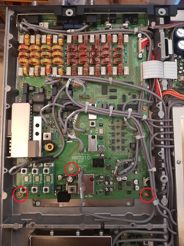
The main goal was reached by re-tighting the 3 screws on the picture.
WOW, what a surprise!
They were definitely not loosen, but ¼ turn of them and the ghost signal dropped down of 10 dB!!
It seems definitely a ground problem, or loop problem.

On my research for EMI this time I took the board a part to check the bottom.
You can see a good number connections to ground and some shields.
Refreshed solder of the ground pads and added 2 more pads
Reinstalled the board, I added other 2 connections to the cover, see picture.
These in particular reduced the signal further 8 dB!

So now the ugly signal is no visible in almost all bands, even without the Scope attenuator inserted.
There is just a weak trace on some bands but fully covered from the band noise.
I am very happy with these results.

This is the worst case. In other bands is even better or not visible at all.

Adding 10 dB attenuation on the scope every ghost signal disappier. Nice!!
I have just a question about the design, see the picture:
The signal R2LO is amplified by IC1651 and through a 100 ohm resistor and a decoupling 1nF capacitor goes directly to the DOUBLE BALANCED MIXER 9A41.
See the picture below.
As I can't find further info about the mixer, I don't know how it can work on the domain of the frequency at the LO (pin 1) input. May be it would be better in this case add a small attenuation pad to help the 64,4 MHz signal (which is quite strong there!) to return to ground a little bit easily, instead to be radiated.
Actually I do not tried modification at that point of the board because the 2 mixers and the IC1651 are closed in a small metallic box. The components there are definitely too small and it is even harder to operate in that conditions.
Any comment would be appreciated.
_______________________________________________________________________
Some notes for me:
After the mixers the interfering signal is much lower (RF output IC1501-2).
A better EMI research must be done. As the reading of the scope were low, I did not spent further time for that. Proper E and H coupling tips must be used together with the Spectrum Analyzer.
I forgot to investigate also on the positive rail of this circuit (around L1654). Next time...


ICOM IC-7700 SCOPE SPUR REDUCTION
12 Jan 2017

After long time I decided to take my IC-7700 a part and clean the dust inside.
As it is an HEAVY radio, this operation was always postponed.
Very nice piece of equipment!!
In the mean time I decided to give a look at the famous spur.

I find the “f0 -36 kHz spur” on the scope very annoying.
I use the radio 99% as IF on 144 MHz for tropo o EME operations and of course the low band noise let me ALWAYS see the spur...
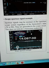
Icom documented the "possibility" of some spurious signals.
The spur is readable on all bands with variable intensity, depending on the band and preamplifier settings (on 14 MHz band it is lower with the preamp in line!).
It is more a psychological problem rather than a real degradation of the receiver characteristics: I really hate seeing it on the waterfall all the time.

The SCOPE UNIT works well, the problem comes from the RF UNIT which introduces an unwanted signal into the SCP_FROM_RF_UNIT input. The SCOPE UNIT therefore “reads” correctly also the spur at about -103 dBm (value is depending of mode or bands).
There is not any kind of interaction with a supposed 36 kHz signal on the SCOPE UNIT. The spur is ABOUT 36 kHz from the fo, changing from mode to mode.
Unwanted signal at the SCOPE UNIT input:
64.4910 MHz in AM or FM
64.4895 MHz in LSB
64.4925 MHz in USB or PSK
64,4105 MHz in RTTY
I measured the level of LO arriving from the PLL UNIT and all was correct.
The signal RX 2nd Lo R2LO coming from the PLL UNIT enter into the RF UNIT and then goes to the mixer IC1501+1502 with the correct levels.
For some reasons a low portion of it is picked up also by the buffer Q1352 which send part of the 1st IF to the scope.


I have had some results on reducing the scope spur acting on C1656 (RF UNIT) which is on the 90° phase shifter circuit. But degrading the RX performance was definitely not the right way...
Did the RF UNIT IMAGE RESPONSE calibration procedure to re-set the correct value again.
I suspected that the unwanted signal was somewhere radiated (after Q1651 the LO level is quite high).
I have put a good number of ferrite cores on the coaxial cables coming in or going out the RF UNIT having only a marginal reduction of the spur only applying a ferrite to the SCOPE BOARD inputs cables SCP_FROM_RF_UNIT + SCPT_FROM_RF_UNIT. I kept that core on the radio.
Another test was to move the coaxial cables on the RF UNIT. As there are a lot of wires it was quite difficult and I never get enough good results (variation +-3 dB).
Only in one CASUAL position the spur level decreased consistently but I was not able to reproduce that again!... That led me thinking that there is a multiple interaction and sitting the cover will modify again the results.
I have finished to resitting every coaxial cable on the RF UNIT on a different way, keeping the 2 wires going to the SCOPE UNIT and the RX_2nd_LO_R2LO more separated possible.
I did not remove the RF UNIT board to make further measurements.
The final result is a spur on the scope lower about 4 dB (+-1 dB depending on the band).
Actually not a big improvement, but better than nothing.
Further, to cancel the spur on the waterfall, I have setted the scope input attenuator at 10 dB for every band. This reduces the sensitivity of the scope but seems to be still usable for general use.
I hope that somebody will use these notes as starting point for further improvements on this clear lack of design.


Scrivi commento
Sergio IK8TNG (martedì, 17 gennaio 2017 00:32)
Ciao e per prima cosa complimenti per la tua esposizione al problema. Non ho più sotto mano il 7700, ma vorrei poterti dare una mano. Ci provo. Appena 10gg fà ho riparato detto rtx, e mi è caduto l'occhio incuriosito ad un flat particolarmente schermato. Questo flat cade direttamente sul display. La butto li, hai pensato che il problema possa essere un loop? Mi spiego, un segnale di provenienza dal survoltore lampade e lcd, che sparato nella zona RF, viene amplificatonper poi ritornare indieteo? Ho la possibilità di verificare su altri due 7700 nei prossimi gg. Queste cose intrigano. Buona caccia.... 73 Sergio IK8TNG Aversa...